

Microphones – Legendary reliability for the stage, studio, conference room, auditorium, and more …
Microphones – Legendary reliability for the stage, studio, conference room, auditorium, and more …
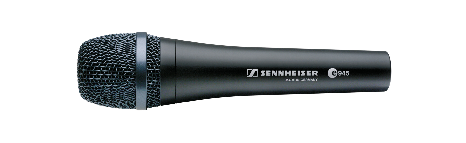
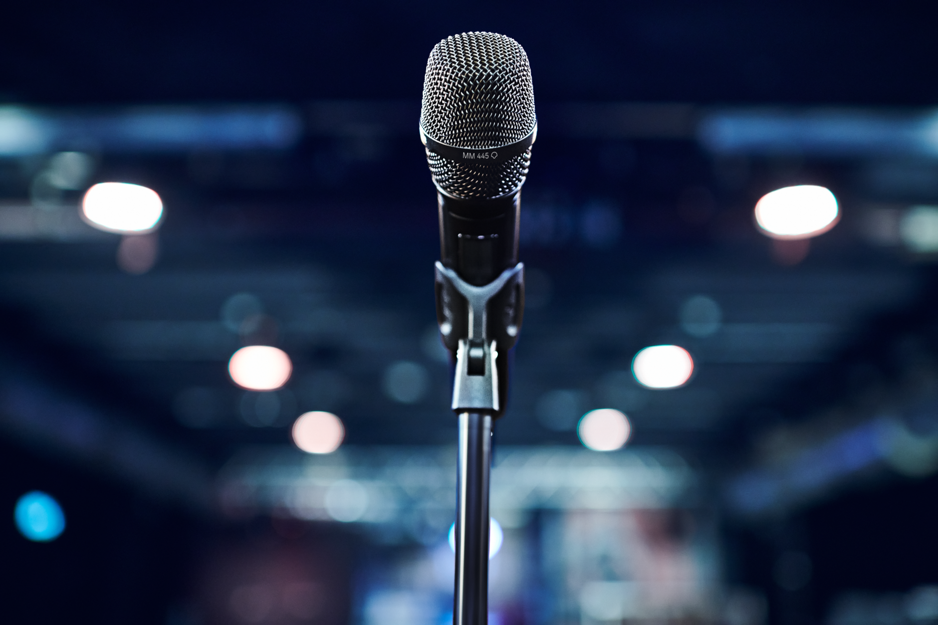
Hit the stage with a live performance microphone you can trust

Hit the stage with a live performance microphone you can trust
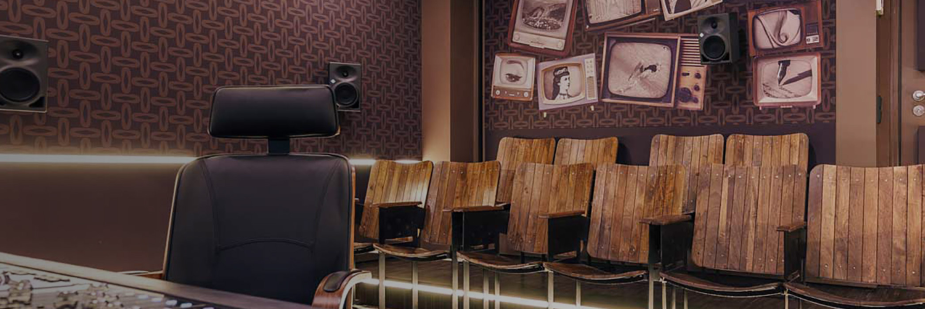


About us
About us